I just wanted to ask whether anyone knew anything about the subject before posting the pictures, etc. We keep running into dead ends with no one knowing anything about it.
Here's the deal:
We are in the process of bringing back to life the swimming pool that came with the house we bought last year. We've had to replace the pump motor (it was burned out). The replacement is an A.O. Smith 230v 1 HP dual-speed motor (STS1102R). The switch to operate it was sold separately. It is also made by A.O. Smith, and is an end cover for the motor that has a High-Off-Low toggle (615332). Neither came with any wiring diagrams, so we are trying to puzzle out which wire goes where. Here are some pictures:
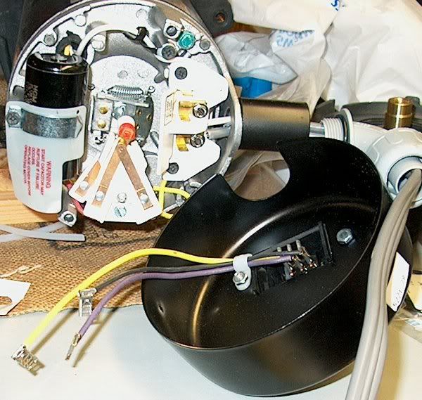
#1 - Motor and inner side of switch:
![]()

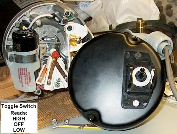
#2 - Motor and outer side of switch (label in lower left corner shows what toggle switch reads):
![]()

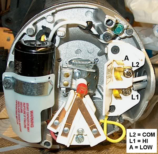
#3 - Close-up of end of motor (I added labels for the connections since there was too much glare in the photo to read them, and inserted, in the lower right corner, what the little label to the side of the connections reads):
![]()

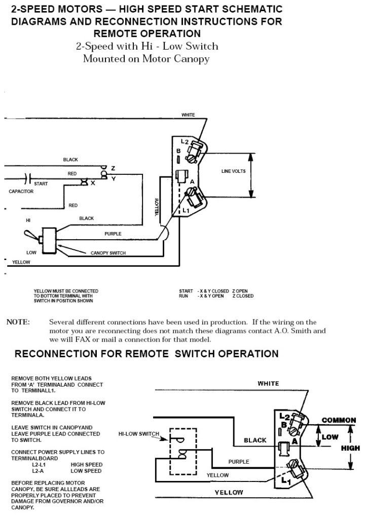
#4 � Wiring diagram from a page in A.O. Smith�s online motor manual (
http://www.aosmithmotors.com/pdf/brochures/3300.pdf ) (page 45) that seemed appropriate (?):
![]()

My husband says with the switch in the 'low' position, there's continuity between the purple and black wires. With the switch in the 'high' position, there's continuity between the purple and yellow wires. On the switch, the yellow wire connects to the position marked 'low' on the toggle, and the black wire to the position marked 'high' on the toggle. The purple wire connects to the position marked "off."
We aren't even sure this diagram is the correct one. It just was the best we could find. We don't want to hook it up wrong and fry something! So, if you, or anyone else here knows anything about this, we'd appreciate some advice.
Thanks!